What would you see through a wormhole?
Science fiction has always fantasized about the idea of traveling impossible distances using instruments that alter the properties of the surrounding space. This is the case of the Portal video game series, in which the protagonist uses the “Aperture Science Handheld Portal Device” to create portals that connect otherwise unconnected points in space. While such structures are referred to as “portals” in the game, their actual name in both academia and popular culture has been “wormholes” since Charles Misner and John A. Wheeler coined the term in 1957 (Misner and Wheeler). Here, they referred to wormholes as points that would connect regions of space and time by means of intense deformations in the space-time fabric. However, it was not until 2014 in the movie Interstellar, when the public was presented with an image of a wormhole that purported to be accurate and in accordance with the laws of physics we know so far (James et al.). It should be made clear, however, that a wormhole has never been sighted due to both the technical difficulties this would entail (Dai and Stojkovic) and the uncertainty that currently exists around its (non)existence. As depicted in several studies (Friedman and Higuchi), the existence of wormholes would require both the possibility of negative energy emergence and closed time-type curves (i.e., time travel). Moreover, if they existed, most probably this type of constructs would close almost immediately after appearing, so the possibility of traveling through them would be limited. This without mentioning that it would not be a comfortable trip due to the intense forces of compression and extension to which our body would be subjected when crossing a region of spacetime with such a curvature. Even so, who wouldn’t be at least a little bit curious to look through one of them from the comfort of their couch?
The ways of representing a wormhole are very varied, starting with the most artistic, through models made with the help of CGI programs (Computer Generated Imagery programs) to the most accurate simulations such as those found in Interstellar. In this post I will try to explain how to replicate the wormhole that appears in this movie, and I will try to do it without showing equations or code (there are already the papers and GitHub for that) and starting from the basis from which I started when I undertook this project a little over a month ago: without knowing anything about the subject beyond general ideas. It is important to emphasize the extreme complexity of everything I am going to deal with here, so I will simplify some details that will not have an impact on the whole, but will be important when it comes to acquiring a deep knowledge of the topic. In the following sections I will explain the basics of the ray tracing technique that we will use for the simulation, how to apply it to the curved space and the steps to follow until the final image is obtained. Figure 1 shows the result I have obtained.
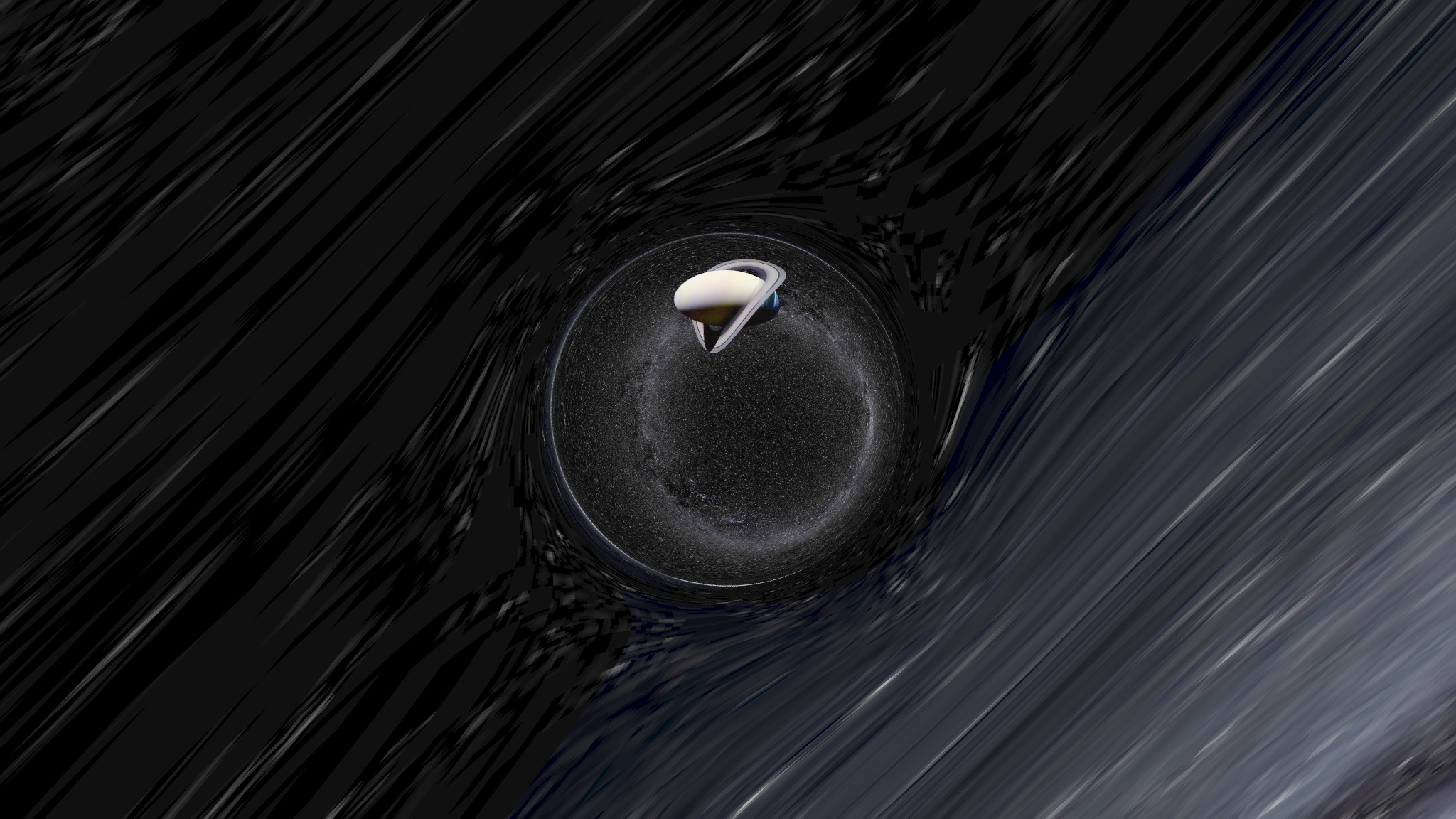 Figure 1: Wormhole image obtained following the method described in this post.
Let’s ray trace
When we look at an object, what do we see? That is the fundamental question we must ask ourselves before starting this project, since the answer will determine our approach to it. When we look at a certain object, our brain is registering the intensity of the light carried by the rays hitting the receptors of our retina. These rays come from the light sources in our environment and acquire one intensity or another depending on the objects they hit before reaching the retina. Thus, when we are outdoors and see a red apple, it is because some rays coming from the sun have hit that specific apple and it has given us back the red part of them. A camera uses a very similar principle to capture a photograph: in the body of the camera is the sensor, organized in pixels forming a grid, and each of these pixels registers the intensity of the light that passes through it. This same principle is applied to generate computer images, the main elements (camera, lights and objects) are placed in the scene and in a process called rendering the trajectory of the rays that hit the camera is traced, also taking into account their bounces and refractions to which they are subjected. This technique is called “Ray Tracing” and it is fundamental in modern rendering processes1 due to the realism they offer.
Ray tracing starts by placing the camera at a point in the scene. Do you remember that a camera has a sensor that forms a grid and in that grid is where the image is projected? We will use this same concept. At a distance from the camera (we will call it focal length) we will place the plane of the screen, as in Figure 2. It seems obvious that we cannot know a priori which rays will reach each pixel of the screen, and tracing all possible rays from the light source seems a strategy doomed to failure since most of them will not even graze the screen. However, we can take advantage of the deterministic behavior of the rays and trace them backwards, from the camera to the scene, bouncing them off the objects until they converge on a light source or get lost in the infinite sea of bounces and refractions. Thus, the concept of the camera becomes just the point from which all the rays depart. With each collision the intensity value of the light ray will change depending on the parameters of the object (a transparent glass ball is not the same as a brown wooden cube). It is important to note that in everyday scenes these rays will move in a straight line between collisions, in no way will they curve their trajectories (this is how light behaves, it generally travels in a straight line), so it will be immediate to know for each moment of time where a ray of light is. This will be one of the points to take into account when introducing the wormhole.
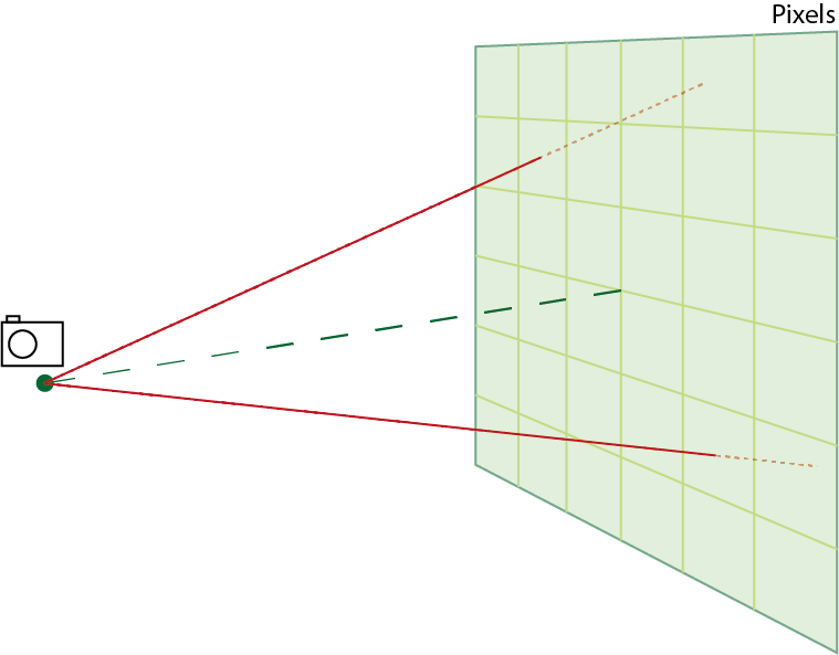 Figure 2: Camera and screen relative position.
It is not worth going into the detail of how to calculate the direction of a ray after a bounce nor its intensity, but I leave here a book that has been very helpful in my still short journey through Ray Tracing: Ray Tracing in One Weekend(Shirley).
Designing a wormhole
There are a multitude of different ways to design a wormhole such that it is physically plausible2. The first time this was achieved was in 1973, when H. G. Ellis (Ellis) and K. A. Bronnikov (Bronnikov) separately developed a mathematical model of the wormhole as we now know it, in which in principle there could be matter transfer between the two sides of the wormhole. This wormhole actually attracted matter strongly toward its throat (the center of the wormhole) at one end, while the repulsion at the other end was equally strong. For this reason, it was called Ellis’ drainhole.
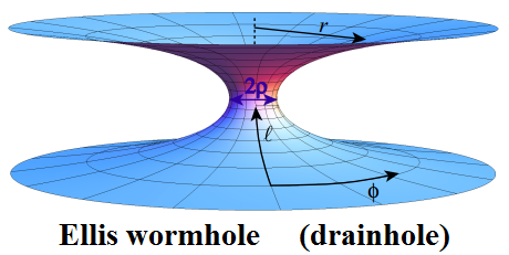 Figura 3: Ellis’ drainhole. Image from (James et al.).
Although in the following years other wormholes with various characteristics were developed (even some that would allow time travel (Morris et al.)), due to its mathematical simplicity we will work with a slightly modified version of Ellis’ wormhole to generate our image. Why using a modified version? The reason is very simple: apparently Christopher Nolan (the film’s director) wanted to have control over the shape of the hole - the radius of the throat and the distance between the ends mainly - and that is something that the Ellis wormhole does not offer, so they developed a modification for the film (James et al.). The animation studio that came up with the whole thing is called DNEG so (oh, surprise) they named their wormhole…. Dneg.
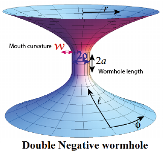 Figure 4: Dneg wormhole. Image from (James et al.).
We will use as parameters for our wormhole a throat radius (\( \rho \)) of 1km and a throat height (\( a \)) of 0.01km and we will place the camera 6.25km from the top mouth of the hole, pointing directly at the mouth of the hole. As we know, two different parts of the universe will be joined, each with its celestial sphere (yes, this is the name given to the sphere around the observer in which the stars are placed), so the camera will be surrounded by a starry sky and will point towards the planet Saturn, which will be on the other side of the hole3. The images are available in the supplementary material to the original paper. To imagine it -although it is not physically correct-, we can think of the hole in the previous figure with a hollow sphere on each side of the throat in whose interior we will place an image with the contents of that portion of the universe, those will be the two celestial spheres. With this we already have all the necessary ingredients to start taking our picture.
Hold on, curves are coming
We have already seen how to deal with rays moving through the flat space we are used to (Euclidean space). However, the very definition of a wormhole implies a deformation of space, curving it and affecting all objects around it, including light rays. For this reason, the trajectory of the rays will change depending on how the wormhole we design deforms space. It does not seem necessary to delve into the equations because it would take too much time to explain them, it is only necessary to know that for each moment in time we can obtain the exact position in which the ray is located. For the interested reader, the equations are in the appendix of (James et al.). We will solve the equations numerically and thereby obtain from which side of the hole the ray comes from and at which point on the corresponding celestial sphere. As we have seen in the previous section, each celestial sphere is actually an image, so we will only have to take the value of the image at the point where the ray has hit, so we will have a mapping between the pixels of the camera (initial point of the rays) and the pixels of the celestial spheres (end point of the rays). The following figure shows a fictitious representation of this process for one of the two celestial spheres.
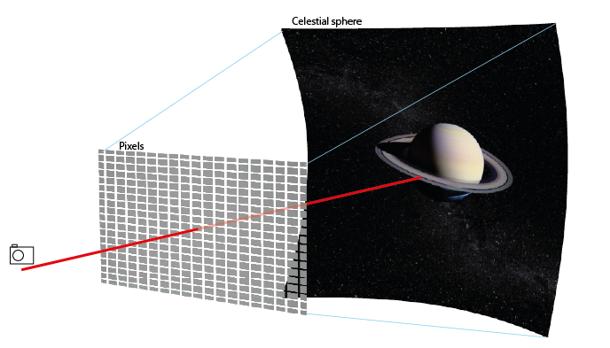 Figure 5: Mapping of the celestial sphere to the screen pixels. The representation is fictitious because we are using a flat space, the wormhole should be located between the screen and the celestial sphere, so the lines would not travel in straight lines.
Once the image has been obtained, we can examine it (Figure 1): we can see that the central part corresponds to the celestial sphere in the part of the universe where the camera is not located (Saturn), while the outer part is a starry sky. This is precisely due to the curvature of space. As the rays do not travel in a straight line, the pixels of the camera sensor receive light from both ends, so it can happen (and it does happen) that two contiguous pixels receive light from far apart portions of the universe, hence we can see both ends of the mouth of the hole at the same time. We also see in the image that the starry sky around the hole is no longer “starry” but a jumble of curved lines. This effect has its origin in the distortion that the hole creates in the space around it. It acts as a gravitational lens, which means that it makes visible light coming from areas that would not be visible if there were no hole.
Another very interesting effect is created at the boundary of the wormhole mouth: at the opposite end of the wormhole from where Saturn is, a secondary image of Saturn (at least a minimal region with brown pixels) can be seen. The primary image of Saturn appears thanks to the rays traveling directly from the planet to the camera. The secondary ones (there are more but they are not visible) come from rays that have traveled longer paths through the wormhole. This effect appears also in black holes and is well known (Tsukamoto et al.). Moreover, since it depends on the rays that have traveled a longer path to reach the camera, its presence depends on the length of the wormhole. In the figure below, this phenomenon can be observed in a hole with a length 100 times longer, so that the second image of Saturn is clearly seen. The curvature of the hole’s mouth has also been modified to obtain this image, causing the deformation in the surrounding space to be larger as explained in the previous paragraph.
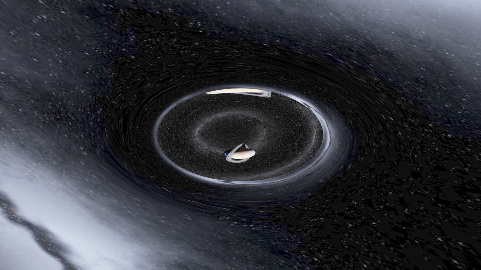 Figure 6: Dneg wormhole image. The increase in the curvature and length of the throat leads to an even greater deformation of the surrounding space.
This concludes this entry in which I have tried to explain how to generate an image of a wormhole using only the equations that govern the light rays in spacetiem and a well-known technique such as ray tracing. I have wanted to convey at all times that this subject is extraordinarily complex and, of course, there are details that I have overlooked for fear of making it even more dense.
The code I wrote to generate all the images is publicly available in a repository on GitHub. It is not as tidy as I would like, but it was my first time using C++/C in many years. Any questions or comments are welcome.
- Misner, Charles W., and John A. Wheeler. “Classical Physics as Geometry.” Annals of Physics, vol. 2, no. 6, Academic Press, December 1957, pp. 525–603, doi:10.1016/0003-4916(57)90049-0.
- James, Oliver, et al. “Visualizing Interstellar’s Wormhole.” Citation: American Journal of Physics, vol. 83, 2015, p. 486, doi:10.1119/1.4916949.
- Dai, De Chang, and Dejan Stojkovic. “Observing a Wormhole.” Physical Review D, vol. 100, no. 8, American Physical Society, October 2019, p. 083513, doi:10.1103/PhysRevD.100.083513.
- Friedman, John L., and Atsushi Higuchi. Topological Censorship and Chronology Protection. 2008.
- Shirley, Peter. Ray Tracing in One Weekend. 2020, https://raytracing.github.io/books/RayTracingInOneWeekend.html.
- Ellis, Homer G. “Ether Flow through a Drainhole: A Particle Model in General Relativity.” Journal of Mathematical Physics, vol. 14, no. 1, American Institute of PhysicsAIP, January 1973, pp. 104–18, doi:10.1063/1.1666161.
- Bronnikov, K. A. “Scalar-Tensor Theory and Scalar Charge.” Acta Phys.Polon.B, vol. 4, 1973, pp. 251–66.
- Morris, Michael S., et al. “Wormholes, Time Machines, and the Weak Energy Condition.” Physical Review Letters, vol. 61, no. 13, 1988, pp. 1446–49, doi:10.1103/PhysRevLett.61.1446.
- Tsukamoto, Naoki, et al. Can We Distinguish between Black Holes and Wormholes by Their Einstein-Ring Systems? 2012.
-
Ray Tracing is not the only technique currently used, but it is one of the most widely used because it offers a good ratio between the final quality of the images and the time spent for rendering. ↩
-
That a wormhole is physically plausible implies that it is a solution of Einstein’s equations, not that it has been observed. ↩
-
Because this is a representation of the hole in fewer dimensions than actually take part, the camera has not been placed in Figure 3. It is good to get an idea for programming purposes to place the camera mentally in the vertical of the throat of the hole, pointing perpendicularly to it. However, in this Figure we are actually representing space-time itself, and all objects must be on the grid, including the camera. ↩